
Introduction
I remember walking into a lab where three mice were prepped and the signal looked flat — dead quiet. In neuro research that quiet is data lost, budgets strained, and late nights multiplied. (We all know that sinking feeling.) Recent internal surveys show labs can lose up to 30% of planned recordings to avoidable hardware or protocol issues — so what really breaks, and how do we stop it? I want to share what I’ve learned from hands-on trials and honest mistakes, then move into practical fixes you can use tomorrow.
Understanding Deeper Fault Lines
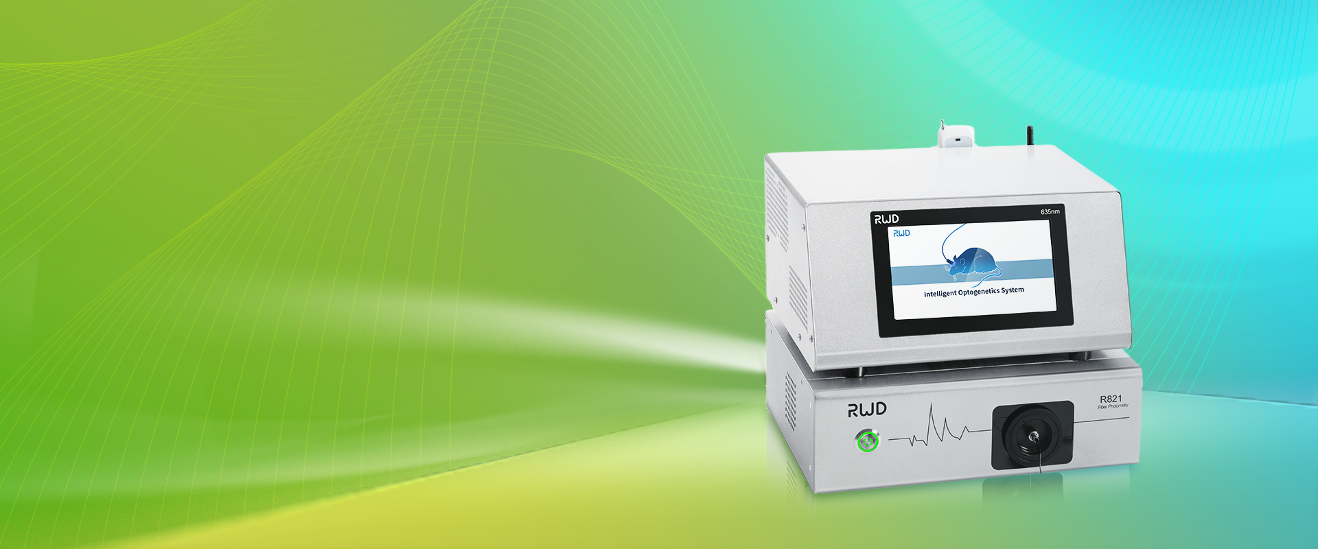
fiber photometry system setups often look simple on paper, yet they hide layers of fragility. Technically, a photodetector paired with an optical fiber and a fluorescent reporter like GCaMP should give clean traces — but reality differs. Poor fiber coupling, drift in excitation LEDs, and mismatched sampling rate all erode signal-to-noise ratio. I’ve seen labs blame biology when the root cause was a loose connector or a contaminated ferrule. Look, it’s simpler than you think: the interface between hardware and animal prep is where most failures begin.
Why do setups fail?
First, routine maintenance is neglected. Ferrules collect dust; optical fiber tips pick up residue. Second, configuration mismatch: acquisition software set at the wrong sampling rate, or filters that cut needed bandwidth. Third, user workflows — hurried implantations, inconsistent anesthesia protocols — introduce variability that no electronics can correct. From my perspective, these are not mysterious faults. They are predictable, and so fixable with checklists and modest investment in training and spare parts.
Looking Forward: Principles and Practical Steps
What’s next is about principles, not gadgets. New technology principles emphasize modularity and reproducibility. When I say modularity, I mean systems where the light path — LED, optical fiber, patchcord, ferrule, photodetector — can be swapped without a full revalidation. That design reduces downtime and isolates faults faster. We should standardize connectors, use calibrated photodetectors, and adopt simple logging to track LED output over time. — funny how that works, right? These moves cut troubleshooting from hours to minutes.
What to evaluate
Here are three practical metrics I recommend when choosing or upgrading a system: (1) stability of excitation output — monitor LED flux over days, not just minutes; (2) end-to-end signal-to-noise ratio — measure with a known fluorescent standard; (3) ease of field service — can a technician swap a module in ten minutes? I prioritize these because they predict long-term success more than raw specs on a data sheet. When labs adopt these criteria, their experiments become steadier, and confidence grows — which is priceless.
Finally, I’ll say this plainly: you don’t need the fanciest rig to get good data. You need the right practices, the right checks, and a culture that values reproducibility. If you want a reliable source for components or a platform that emphasizes modularity, I’ve found resources that help accelerate setup and support. For practical tools and components, consider visiting BPLabLine — they helped my team shorten downtime and improve signal fidelity in ways that mattered on the bench and in our papers.