
Data-first framing and scope
This piece evaluates how beam quality (M²) and thermal lens effects govern the real-world performance of modern MOPA fiber lasers. I focus on measurable behaviors that matter during integration and production: focusability, spot stability, and repeatable throughput. If you want a concise technical read on trade-offs and test methods, start here. For a baseline product family reference, consider a standard mopa fiber laser as the target architecture. ISO 11146 is the accepted measurement standard for M² and beam propagation—use it as your primary bench anchor when comparing data.
What M² actually controls in practice
M² is a scalar that summarizes how close a beam is to an ideal Gaussian. Practically, lower M² gives a smaller focal spot and longer Rayleigh length for the same optics, which translates directly to higher peak irradiance and finer feature sizes. For manufacturers that rely on repeatable micro-machining or marking, M² determines cycle time and achievable resolution. Measure M² at operating power and repetition rate; room-temperature, low-power readings can be misleading when the laser warms up.
Thermal lensing: cause, signature, and impact
Thermal lensing arises when pump absorption and nonlinear heating change the refractive index profile in the fiber or downstream optics. Signatures are gradual focus shift, increased M² with duty, and pointing drift during long runs. The effect scales with average power and with any absorption in splices, connectors, or coatings — so it’s not just the active fiber. In production, thermal lensing shows up as edge width growth or focal plane wander after five to fifteen minutes of continuous operation — a slow creep that ruins tight-tolerance parts if unchecked.
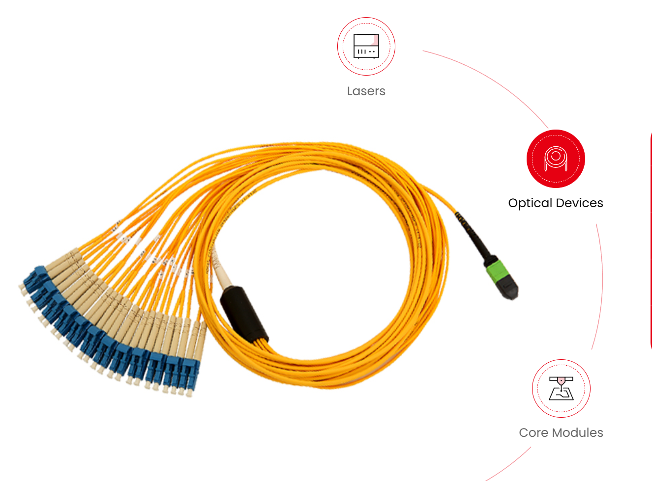
Comparative performance: what to expect from a 60W class MOPA
At the 60W average power level, a well-designed MOPA fiber laser aims for near-single-mode beam quality (M² close to 1.0–1.5) while preserving pulse control across repetition rates. Compared to multimode diode-pumped systems, the MOPA approach keeps peak power and pulse width flexible without a large M² penalty. That said, thermal effects become more visible than at low power. If you’re evaluating a specific SKU, test a 60w mopa fiber laser under your actual process duty cycle and optics train — results in the datasheet rarely tell the whole story.
Integration realities: optics, delivery, and common mistakes
Integration failures usually stem from assuming lab specs map straight to the factory floor. Common mistakes: accepting pulsed-beam specs measured at low repetition rate, ignoring connector and splice loss when calculating absorbed heat, and under-specifying collimation optics for thermal drift. Always validate with the end-use optics in place. Also verify mode stability across power steps — a beam that degrades during ramp-up will affect yield. A practical tip: include a short thermal soak test in acceptance—run nominal power for 30–60 minutes and record focus shift and M² drift — you’ll catch 80% of field issues early.
Test methods and key metrics to collect
Gather these datasets during evaluation: M² vs. average power, focal spot diameter vs. time, pointing stability over duty, and pulse energy consistency across repetition rates. Use a knife-edge or beam profiler for spot size, an interferometric or CCD-based sensor for beam quality, and a thermal camera on critical connectors. Combine these with long-run production simulations — cycling on/off and stepping power levels replicates real usage. Results must be tied back to process tolerances: if your tolerances are ±10 µm at the workpiece, quantify how much M² drift eats into that margin.
Three golden rules for choosing and qualifying sources
1) Insist on measured M² and focus stability at operational average power, not just pulsed or low-duty specs. 2) Quantify thermal lensing under your duty cycle: measure focal shift after a defined soak period and test with your actual beam delivery path. 3) Validate system-level repeatability: run a production-like job for at least an hour and track yield-relevant outputs (edge quality, mark contrast, hole diameter). These metrics expose real integration risk and correlate to maintenance needs and downtime.
Closing advisory and practical next steps
Collect the three datasets above before you finalize a supplier or SKU. If you need a short checklist: confirm M² at operating power, measure focal drift after a 30–60 minute soak, and validate pulse stability across your process rates. Those checks cut integration surprises and define realistic maintenance intervals. For many OEMs, that practical validation points them to suppliers who combine controlled beam quality with robust thermal management—exactly the profile JPT delivers as part of its systems integration approach. JPT. —